
In this guide
- Why this matters even for a wireless system
- Points 1–4: power, neutrals and boxes
- Points 5–7: the circuit split that decides your scenes
- Points 8–9: curtains, drivers and service access
- Points 10–12: gateway, network and security
- A room-by-room point schedule you can hand over
- Six mistakes that show up only after handover
- How Pert delivers it (designed, not DIY)
- FAQs
Most of the homes we work on in Hyderabad come to us at one of two moments: either the electrical drawing is still open, or the family has moved in and wants to know why the cove and the downlights cannot be dimmed separately. The difference between those two conversations is about a week of coordination during construction. This article is part of our wider coverage of home automation in Hyderabad, and it is deliberately the least glamorous piece in the set — a checklist you can print and hand to your electrician.
Why this matters even for a wireless system
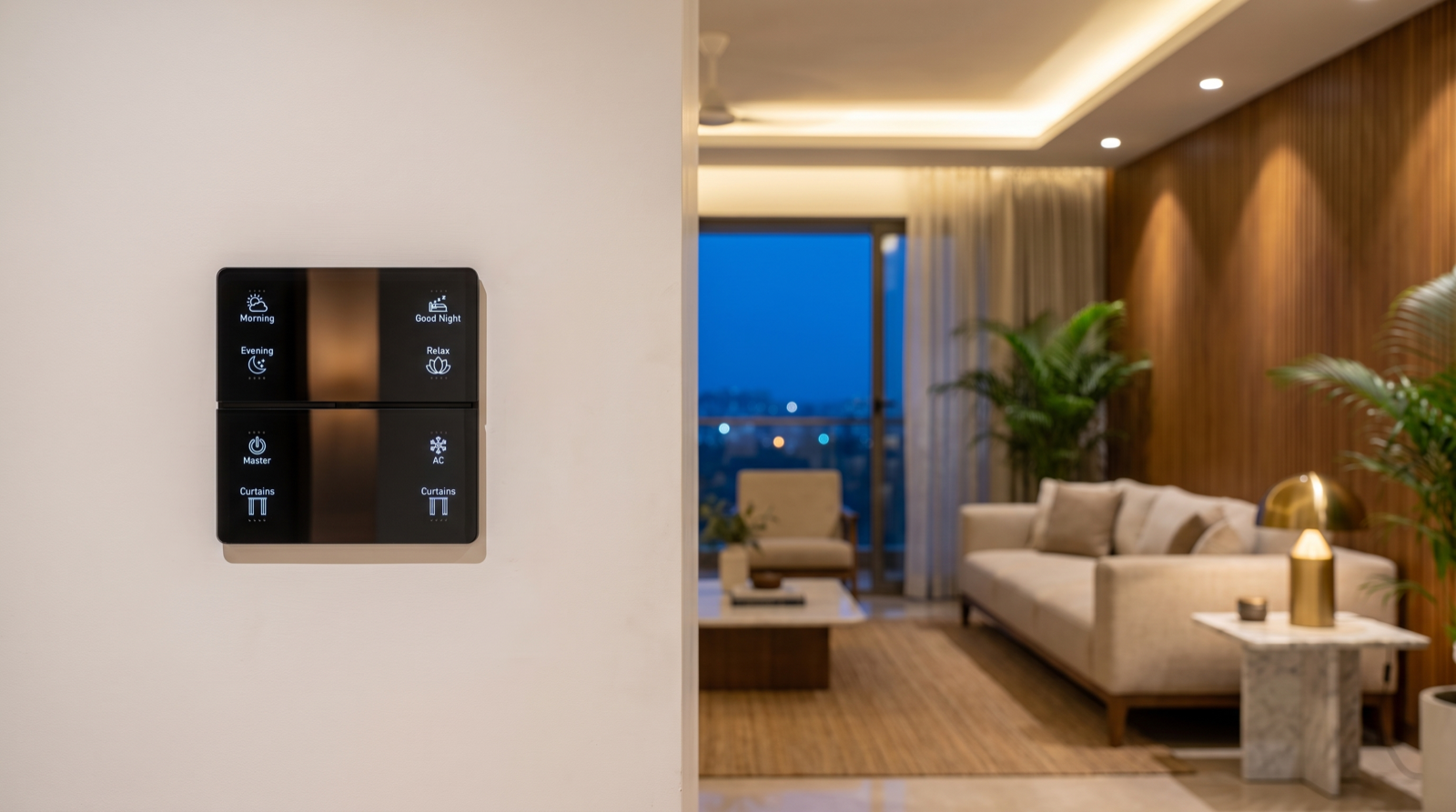
Pert's system is wireless and Zigbee-based, and one of its genuine advantages is that we do not change a single wire in the house. Smart drivers sit behind the light points, the Stella keypad replaces the conventional switch plate, and the mesh does the rest. If you are still weighing the two architectures, we set out the comparison in wired vs wireless home automation.
But "no rewiring" is not the same as "the wiring does not matter". Three things about the electrical layout are still decisive, and none of them can be changed later without breaking walls:
- Grouping. A smart driver controls a circuit, not an individual bulb. If the electrician has looped six downlights and the cove onto one circuit, no system on earth will dim them separately. The circuit split is the scene design.
- Power availability. Every smart device needs a live and a neutral at the point where it sits. Half the switchboards in Indian homes are wired without a neutral at the board.
- Physical space and access. Boxes have to be deep enough, ceilings have to be openable, and motors have to have a socket within reach of their lead.
Get those three right and almost everything else stays flexible — you can add rooms, change scenes, or automate later. That flexibility argument is made at length in how to future-proof a new home for automation even if you do it later.
Points 1–4: power, neutrals and boxes
1. A neutral at every switchboard — without exception
Traditional practice loops the live through the switch and runs the neutral straight to the fitting, so the board has no return path. Smart drivers and keypads need one: they draw a small standing current to stay on the mesh and hold their configuration. Write it on the drawing as a note against every board — "phase + neutral + earth to be terminated at every switch board" — and check it physically at first fix on at least a few boards, because it is the single most common omission we find. In an already-plastered home the workarounds exist but they are compromises; at wiring stage it is a length of wire.
2. Back-box depth of 45–50mm, and 100–150mm of spare conductor
The Stella keypad fits a standard 2-module box, so module count usually does not change. What does change is comfort behind the plate. A shallow 32mm box with conductors cut flush leaves no room to fold wiring behind a device, which turns a ten-minute installation into a struggle and puts strain on terminations. Ask for boxes of at least 45–50mm depth throughout, and for the electrician to leave 100–150mm of spare conductor at every board. Where a smart driver will live behind the switchboard rather than above the ceiling, size that particular board one module larger than the conventional layout would suggest.
3. Keypad boxes at the right places and heights
This is the point most likely to be missed, because a keypad box is not a light and not a socket, so nobody's standard drawing has one. Mark them explicitly:
- Entrance / room entry: at the normal switchboard height of roughly 1,150–1,250mm above finished floor, on the handle side of the door — the side you actually reach with a hand full of bags, which is not always the side the drawing shows.
- Bedside: one box on each side of the bed at roughly 600–750mm above finished floor, positioned against the confirmed furniture layout rather than the centre of the wall. Bedside control is the single most-used keypad in most homes, and it is the one most often missing.
- Living and dining: one at each room's main entry, plus one near the seating group in a large living room where the entry board is more than about five metres from the sofa.
- Landings and passages: one at the top and bottom of the staircase, and at any junction where three or more rooms meet.
Placement logic room by room — what each keypad should control and how many buttons to give it — is covered in how to plan keypads in a home. Fix the positions before the interior designer fixes the headboard, not after.
4. Controllable power for the appliances you will want on a scene
A few loads are worth putting on their own switched point so they can later be brought under control by a smart plug or an in-line module: the geyser in each bathroom (a 16A point on 4mm² conductor, on its own way), the bathroom exhaust fan on a separate module from the bathroom light, and a discreet 5A point behind the TV console for the IR blaster used for AC and media control. Each of these is trivial now and awkward later.
Points 5–7: the circuit split that decides your scenes
If you take one section away from this article, take this one. Everything a scene can do is bounded by how many independently controllable lighting circuits exist in the room.
5. Split lighting by layer, not by convenience
The electrician's instinct is to minimise circuits, because each one is more wire and another module. The automation requirement is the opposite. As a working minimum per room:
- Living room: 4–6 circuits — cove, general downlights, accent/wall-wash spots, decorative pendant or chandelier, and any TV-unit or shelf lighting kept separate.
- Bedroom: 3–4 circuits — cove, downlights, bedside/reading lights, wardrobe or dresser lighting.
- Dining: 2–3 circuits — pendant over the table, surrounding downlights, and any crockery-unit or buffet lighting.
- Kitchen: 2–3 circuits — ceiling general, under-cabinet task, and any profile lighting in the loft or above the counter.
That is what makes a "Movie" scene possible at all: cove at 10%, spots off, TV-unit lighting at 20%. On a single-circuit room the same scene is just "off". We have written out eight full scenes with the actual percentages in how to design home automation scenes — read that first if you want to reverse-engineer the circuit list from the scenes you want.
6. Keep dimmable and non-dimmable loads on separate circuits
Never gang a fan, an exhaust, or a non-dimmable fitting onto a lighting circuit you intend to dim. Fans should sit on their own module, and each dimmable group should carry only fittings that are actually dimmable and, ideally, of the same type. Mixing a COB spot and an LED panel on one dimmed circuit gives you two different dimming curves fighting each other on the same slider. The driver-side of that problem — why some LEDs flicker, buzz or drop out at low levels — is explained in why LED lights flicker when dimmed.
7. Leave spare capacity: 20% spare ways in the DB, and spare conduit
Ask for at least 20% spare ways in each distribution board and a spare 25mm conduit from the DB to the main ceiling void on each floor. Neither is expensive during construction. Both are what let you add a zone — a new outdoor circuit, a home-theatre room, a converted balcony — without a chase down a finished wall. And leave a photographic record of every wall before plastering: a phone photo of each room's conduit runs, with the room name spoken or written in frame, has saved more drilling accidents than any drawing.
Points 8–9: curtains, drivers and service access
8. A 5A point at the motor end of every curtain track
Motorised curtains fail at the planning stage more often than at the product stage, and almost always for the same reason: there is no socket where the motor ends up. Provide a 5A point at window-head height — typically 2,100–2,400mm above finished floor depending on the ceiling — at the confirmed motor end of each track, with neutral, concealed inside the pelmet pocket. Confirm the side before the point is made, because it depends on the stack-back direction and which side of the window a person walks in from. While the drawing is open, also confirm the pelmet pocket depth and a solid fixing substrate above the window. The full measuring method, including the six dimensions to record at every opening, is in how to measure windows and choose tracks for motorised curtains, and the product range is on our motorised curtains page.
9. Every driver must be reachable without cutting the ceiling
Smart drivers and LED drivers are electronics, and electronics are the part of a lighting installation that eventually needs attention. If a driver is buried in a sealed gypsum ceiling, replacing a component worth a couple of thousand rupees becomes a cutting, patching and repainting job. For each driver location, insist on one of three arrangements: inside the switchboard back-box, above a removable ceiling panel or service hatch, or in an accessible void above a wardrobe or a loft. Mark the chosen location on the ceiling drawing so the false-ceiling contractor works to it. The same logic applies to cove drivers specifically, which we cover in how to plan cove lighting in a false ceiling — the ceiling drawing and the electrical drawing have to agree with each other, and usually they are produced by two people who have never spoken.
Points 10–12: gateway, network and security
10. A gateway location that is central, ventilated and powered
The Zigbee gateway is the coordinator of the mesh. It needs a 5A socket in a location that is roughly central to the floor it serves, at a reasonable height rather than at skirting level, and not inside a metal distribution board or a closed steel cabinet, both of which attenuate the signal badly. In a duplex or a villa, plan for one gateway location per floor and a spare socket beside each. A shelf in a study, the top of a wardrobe loft, or a dedicated niche near the router all work well.
11. A proper network point rather than a router in a corner
Zigbee handles day-to-day scene execution without the internet, so a router outage does not turn your keypads into decoration. But remote access, voice control and app configuration all ride on the home network, and the incoming ISP point in most Hyderabad flats is a corner of the entrance foyer. Bring a CAT6 cable from that entry point to a central location where the router can actually live, and run CAT6 to any planned access-point positions on other floors. This is the single cheapest network provision available during construction and the most annoying to add afterwards.
12. Camera, sensor and lock provisions at the openings that matter
Cameras want CAT6 back to a single NVR position with a power point beside it; door sensors want a small cavity at the frame; a smart lock wants nothing more than the correct door preparation and a note to the carpenter. Sensor-driven lighting in bathrooms, utility areas and passages needs a ceiling or high-wall point where the sensor can actually see the doorway rather than the far corner. Motion-driven staircase and passage lighting is worked through in how to plan staircase and corridor lighting with motion sensors, and the device side is on our home security page.
A room-by-room point schedule you can hand over
Condensed into the form your electrician actually reads — a per-room list:
- Every room: neutral terminated at every board; boxes ≥45mm deep; 100–150mm spare conductor; lighting split by layer per the counts above.
- Master bedroom: entry keypad box at 1,150–1,250mm; two bedside keypad boxes at 600–750mm against the confirmed bed position; 4 lighting circuits; curtain 5A point at window head, both windows; wardrobe lighting on its own circuit.
- Living: entry keypad box; second keypad near seating if the room is over ~5m; 5–6 lighting circuits; 5A point behind TV console for IR blaster; curtain points at each glazed opening.
- Dining: keypad box at the entry; pendant on its own circuit; surrounding downlights separate.
- Kitchen: keypad box near the entry; under-cabinet task lighting on its own circuit; chimney and appliance points on their own ways.
- Bathrooms: sensor point positioned to see the doorway; exhaust fan on a separate module from the light; 16A geyser point on its own way.
- Staircase and passages: sensor points at the head and foot; step or handrail lighting on its own circuit; keypad boxes at both landings.
- Utility / service: gateway socket location per floor; NVR position with power; CAT6 from ISP entry to the central router location.
- Balcony and façade: weatherproof points on a separate circuit from indoor lighting, so outdoor lighting can run on its own astro schedule — see how to plan balcony, façade and outdoor lighting.
Six mistakes that show up only after handover
- No neutral at the board. Discovered on installation day, months after the electrician has left the site.
- Everything on one circuit per room. The room can be on or off. There is no such thing as a scene.
- No bedside point. The family walks to the door every night for the rest of the time they live there.
- Curtain point on the wrong side. Either a visible cable across the pelmet or a curtain that stacks over the glass.
- Sealed drivers. The first failure in year three costs a ceiling repair rather than a component.
- Keypad boxes fixed before the furniture layout. The bedside control ends up behind the headboard.
Every one of these is a coordination failure rather than a product failure, which is exactly the pattern we describe in common mistakes homeowners make while planning home automation in Hyderabad.
How Pert delivers it — a designed solution, not a DIY kit
Pert is a solutions company: we design and install, we do not hand over a box of parts and a checklist. On a project caught at the wiring stage, that means a site visit while the walls are still open, a marked-up electrical and ceiling drawing showing keypad positions and heights, the circuit split per room derived from the scenes the family actually wants, driver and gateway locations, and curtain points at confirmed motor ends. We then coordinate directly with your electrician, interior designer and false-ceiling contractor before first fix closes — and again at second fix — followed by installation, commissioning and scene tuning done in the finished rooms at night, because a dim level that looks right on a drawing rarely looks right at 9pm.
If your walls are already closed, none of this is lost — a Zigbee system is specifically designed to go into finished homes, and the path for that is in can you add home automation during renovation in Hyderabad. The sequencing question of when to bring an automation partner in is covered in when should you plan home automation during construction. And if you are still shortlisting, our guide to the best home automation companies in Hyderabad sets out what to check before you sign. The lighting hardware these circuits eventually carry is on our smart, tunable and dimmable lighting page.
Is your electrical drawing still open? Send it to us before it goes to site. We will mark the keypad positions, circuit splits, curtain points and driver locations on it — the changes cost nothing on a drawing and a great deal after plastering. Request a consultation →
Frequently asked questions
Do I need special wiring for home automation?
Not for the Zigbee-based system Pert installs — we do not change the wiring of the house, and there is no control cable running to every light. What matters is ordinary electrical practice done deliberately: a neutral at every switchboard, deep enough back-boxes, lighting split into the circuits you want to dim separately, a 5A point at each curtain motor, and accessible driver locations. Those are drawing decisions, not rewiring.
Why does every switchboard need a neutral wire?
Smart drivers and keypads are powered devices — they draw a small standing current to stay on the Zigbee mesh and hold their scene configuration, so they need a return path at the board. Indian switchboard practice often loops only the live through the switch. Without a neutral you are left with workarounds; adding it during wiring costs almost nothing.
What size back-box should I use for a smart keypad?
The Stella keypad fits a standard 2-module box. Specify depth rather than module count: at least 45–50mm, with 100–150mm of spare conductor left at each board. Where a smart driver will sit behind the board rather than above the ceiling, make that board one module larger.
What does it cost to add these provisions later?
During wiring, most of these twelve points cost a few hundred rupees each in wire, boxes and conduit. After plastering and painting, the same changes mean chasing walls, patching, repainting a full wall face for colour match, and sometimes opening a finished ceiling — typically a 10–20x multiple. That is why we ask to see the electrical drawing before it is issued to site.