
In this guide
- The channel, not the switch, is the unit of planning
- What each fixture actually draws
- Maximum load: why you derate an LED channel
- Minimum load: the reason one spot flickers
- Inrush, driver counts and nuisance tripping
- How to group fixtures into channels
- Neutrals, MCBs, cabinets and driver locations
- A worked 3BHK channel schedule
- Points to leave before plastering
- How Pert delivers it (designed, not DIY)
- FAQs
This article is part of our wider coverage of home automation in Hyderabad, and it deals with the least glamorous and most consequential part of a lighting design — the electrical arithmetic underneath it, which is invisible when it is right and impossible to ignore when it is wrong.
The channel, not the switch, is the unit of planning
In a conventional home the planning unit is the switch: one switch, one group of lights, on or off. In an automated home the planning unit is the dimming channel — one controllable output from a dimmer module, carrying one group of fixtures that will always brighten, dim and colour-shift together, for ever.
That distinction has a consequence people consistently underestimate: a scene can only address a channel, never a fixture inside one. If your cove and your general downlights share a channel, then no scene in the system can ever put the cove on at 40 percent with the downlights off, because the hardware has no way to tell them apart. Every lighting effect you will ever want has to exist as a separate channel on day one. This is why a living and dining area that looks like “three switches” on a builder's drawing is properly seven to nine channels, and why the channel count — not the fixture count — is the number that drives the size and cost of the control hardware.
So the sequence is: fix the lighting design and the scenes first, derive the channel list from the scenes, and only then check each channel against the four electrical limits below. Doing it in the other order — buying a four-channel module and then deciding what to plug into it — is how homes end up with a cove permanently tied to a downlight grid.
What each fixture actually draws
Load planning starts with honest per-fixture numbers. These are the figures we work with for typical good-quality residential fixtures in Indian homes; check them against the actual products specified, because a decorative fixture can be double the equivalent recessed one.
- Recessed downlight (general lighting): 7W to 9W each. The workhorse of a bedroom or corridor grid.
- COB spot (accent, wall graze, artwork): 10W to 15W each, occasionally 20W for a high-ceiling or long-throw spot.
- Surface or panel light: 12W to 24W depending on size — a 600x600 panel is typically 36W to 40W and is a serious load if you have several.
- 24V LED strip in a cove: 4.8W per metre for a light decorative glow, 9.6W per metre for normal cove use, 14.4W per metre for a bright or long-throw cove. A 12-metre living room cove at 9.6W/m is 115W before driver losses — add roughly 10 to 15 percent for the driver, so budget about 130W.
- Under-cabinet or niche strip: usually 4.8W to 9.6W per metre over short runs, so 20W to 50W per group.
- Linear or decorative pendant: anywhere from 15W to 60W. Confirm from the actual fitting, never from a category average.
- Tunable white fixtures: treat as the sum of both channels at full — a tunable 10W fixture can draw close to 10W at any mix, but some designs peak higher at 50/50, so use the manufacturer's maximum figure rather than the nominal one.
As a sanity check on the whole home, a well-designed layered lighting scheme lands at roughly 10 to 12W of connected load per square metre. A 1,600 sq ft (about 150 sq m) three-bedroom flat therefore carries something like 1,500W to 1,800W of installed lighting — while typically running at 150W to 300W on an ordinary evening, because layered dimmed lighting almost never operates at full. Which fixture type belongs where is a separate question, covered in our guide to panel vs COB vs strip vs spot lighting.
Maximum load: why you derate an LED channel
A dimmer channel marked 300W is almost always rated against a resistive filament load — an old incandescent bulb, which draws a clean, steady, in-phase current. An LED fixture is nothing like that. It is a switched-mode electronic load with a capacitor at its input, a power factor typically between 0.5 and 0.9, and a current waveform full of harmonics. The heat and stress it puts on the dimmer's switching device at a given wattage is considerably higher than a filament lamp of the same rating.
The working rule, and the one we design to:
- Load an LED channel to 30 to 50 percent of its stated resistive rating. A 300W trailing-edge channel is a 100W to 150W LED channel. A 400W channel is a 130W to 200W LED channel.
- Then leave 20 percent headroom on top of that. Design each channel at no more than about 80 percent of the derated figure, so that swapping a 7W downlight for a 12W one in three years does not silently push the channel over its limit.
- Never sum a module's channels to its total. A four-channel module marked 1,200W frequently has a total simultaneous capacity well below 4 x 300W, because the shared heatsink and common supply are the real constraint. Read the module total, derate that too, and plan against the smaller of the two limits.
- Ventilation is part of the rating. Those wattage figures assume the module is mounted in free air in a ventilated enclosure. Stacked tightly in a sealed cabinet in a Hyderabad summer, a module that is nominally within spec will run hot, and heat is the main reason dimmers fail early.
In practice, a properly derated channel comfortably carries about 10 to 14 recessed 7W downlights, or 6 to 8 COB spots, or 10 to 15 metres of 24V strip — and, as the next two sections explain, the wattage is often not even the binding constraint.
Constant-voltage strip is a different animal
A 24V LED strip is not dimmed on the mains side. It runs from a driver, and the dimming happens either on the DC output (a dimmable constant-voltage driver taking a control signal) or by feeding the driver a dimmable mains supply it is explicitly designed to accept. Chopping the mains upstream of a non-dimmable driver is the single most common cause of a cove that buzzes, steps, flickers, or simply drops out at 30 percent. Specify the driver and the dimming method together, as a pair, at design stage — the full explanation of why is in why LED lights flicker or buzz when dimmed, and the physical detailing of the cove itself is in how to plan cove lighting in a false ceiling.
Minimum load: the reason one spot flickers
Maximum load gets all the attention; minimum load causes more complaints. Most mains dimmers declare a minimum load of 10W to 20W, and some older or cheaper designs want 25W or more. Below that threshold the dimmer cannot maintain the small standing current its own electronics and switching device need to behave predictably, and you get the classic symptom set:
- Flicker or shimmer at low levels, worst in the bottom third of the dimming range.
- A dead zone — the light jumps from off straight to 25 or 30 percent instead of fading up smoothly.
- A faint ghost glow when the fixture is supposed to be fully off.
- An audible tick or buzz from the fixture or the module at particular levels.
The trap is that this appears at the end of a project, on exactly the channels that seemed simplest: the single 5W mirror light, the one 7W spot over the entrance console, the lone niche fixture. Each got its own channel because it does its own thing — and each is now well under the dimmer's minimum.
Three ways to plan around it, in order of preference:
- Never leave a channel with a single small fixture. Group three or four fixtures so the channel clears its minimum with margin. Two 7W downlights on a 15W-minimum channel is not margin; it is a coin toss.
- Move small isolated fixtures to low-voltage. A 24V constant-voltage channel dimming on the DC side has no minimum-load problem, which makes it the right answer for mirror lights, niche lights, joinery strips and other small standalone effects.
- Where a lone mains fixture is genuinely unavoidable, specify a driver and dimmer pairing tested together for that load. Do not assume any dimmer works with any LED — compatibility between a specific driver and a specific dimming curve is a real, checkable property, not a generality.
Inrush, driver counts and nuisance tripping
This is the limit that most often bites in homes where the wattage arithmetic looked fine. Every LED driver has an input capacitor, and at the instant it is energised that capacitor is effectively a short circuit. For a few hundred microseconds a single small driver can pull 10 to 40 amps. Steady-state it settles back to a fraction of an amp and the channel reads as lightly loaded — but the switch-on transient is the stress that actually matters.
Put ten drivers on one relay or dimmer output and energise them simultaneously, and the combined spike can weld a relay contact, damage a switching device, or trip a 6A MCB — even though the running load is only 80W. The tell-tale symptom is a breaker that trips only when a big scene runs, and never during ordinary use.
The planning rules:
- Cap at roughly 8 to 10 individual drivers per channel, regardless of wattage. If the module publishes a maximum capacitive load in microfarads, use that figure instead — it is the more precise version of the same constraint.
- Fewer, larger drivers beat many small ones. One 100W driver feeding a cove run presents far less aggregate inrush than ten 10W drivers, and is easier to service. It also means one point of failure, so keep long runs split sensibly between zones.
- Stagger the scene ramp. A well-configured system fades channels up over one to two seconds with small offsets between them rather than switching everything at t=0. This is a commissioning setting, not a hardware purchase, and it removes most inrush problems on a system that is otherwise correctly sized.
- Use C-curve MCBs on lighting circuits carrying many drivers. A B-curve breaker trips at three to five times its rating; a C-curve tolerates five to ten times, which is the appropriate characteristic for a load with a large, brief, entirely normal starting spike.
How to group fixtures into channels
Once the electrical limits are known, grouping is a design decision with a small number of hard rules.
Rule 1 — identical hardware only
Everything on one channel should be the same fixture type, the same wattage, the same colour temperature and, ideally, the same driver model. Two different LED drivers respond to the same dim signal on different curves: at 20 percent one is at 20 and the other is at 8, and a group that is electrically fine looks visibly broken. Mixing a 2700K fixture with a 4000K one on a single channel is worse still, because you can never separate them and the mismatch reads as a fault in every scene.
Rule 2 — separate anything a scene must separate
Write your scenes before your channel list. If any scene in the house needs the cove on and the downlights off, that is two channels. If the artwork spots should stay up while the general light drops for a film, that is another. The worked scene examples are the fastest way to discover which separations you actually need, and it is far cheaper to discover them on paper than after the ceiling closes.
Rule 3 — group by function, not by geography
The instinct to put “all the lights on the left half of the room” on one channel produces groups nobody ever wants to control. Group by the job the light does: general, cove, accent, task, decorative. Left and right rarely matter; ambient versus accent always does.
Rule 4 — symmetry gets its own channels where it matters
Bedside lights are the standard example: left and right must be separate channels, because the entire point is that one person can read while the other sleeps. The same logic applies to a two-desk study or a shared children's room.
Rule 5 — leave spare ways
Plan two spare channels per control cabinet, and leave physical DIN space for one more module. Homes add lighting: a new balcony fixture, a mirror light after the bathroom is redone, a strip inside a wardrobe fitted two years later. Spare ways turn those into an afternoon's work instead of a new cabinet.
Neutrals, MCBs, cabinets and driver locations
A neutral at every board
Traditional Indian wiring often carries only the live and switched live down to a switchboard, with the neutral looped at the ceiling rose. Automation modules and smart dimmers need permanent power while the light is off, so a neutral must be terminated at every switchboard and every keypad back-box. Without it, the fitting either cannot be installed or must trickle current through the load, which is exactly what causes ghost glow in retrofits. Adding neutrals at conduit stage is close to free; adding them afterwards means chasing finished walls.
Circuit sizing
At 230V a 6A lighting MCB gives a theoretical 1,380W; design to about 1,000W to 1,100W per 6A circuit to keep a sensible margin. Run lighting in 1.0 or 1.5 sq mm cable, and split the home into several lighting circuits rather than one — typically one per floor or one per two or three rooms — so that a fault in a bathroom does not take the whole house's lighting, and so that no single MCB is asked to swallow the combined inrush of thirty drivers.
The control cabinet
Dimmer modules, relay modules and drivers need a real home. Plan a ventilated enclosure of at least 300 x 400mm for a 2BHK and 400 x 600mm or larger for a 3BHK or villa floor, located next to or near the distribution board, at a height that can be reached without a ladder, with a door that opens and space around each module. The two failures we see repeatedly are a cabinet sized to exactly today's module count with no spare DIN rail, and a cabinet sealed behind permanent joinery so that servicing it means dismantling a wardrobe.
Driver locations
Remote drivers for coves, strips and low-voltage spots go above a corridor false ceiling behind a marked access hatch — never sealed above a living room or bedroom, and never buried inside a plastered box. Drivers are the shortest-lived component in a lighting system and the one most likely to need replacing in year six. Keep each driver's location recorded on the as-built drawing, and keep the run length from driver to strip within the manufacturer's limit so voltage drop does not dim the far end of a cove.
A worked 3BHK channel schedule
A representative 1,600 sq ft three-bedroom flat, planned properly. Channel counts are dimmable outputs; curtains and security devices are controlled separately and are not dimming channels.
- Living & dining — 8 channels. Cove (about 130W), general downlights (about 90W), feature-wall graze (about 60W), artwork spots (about 40W), dining pendant (about 40W), dining surround downlights (about 55W), joinery and niche strips (about 35W), switched sockets for lamps. Roughly 450W connected, spread across channels each sitting near the middle of its derated range. The design logic behind these eight is in how to plan living and dining room lighting layers.
- Master bedroom — 6 channels. Cove, general downlights, bedside left, bedside right, wardrobe and dresser, balcony or bay. Bedside left and right are separate on principle, and each is grouped with enough fixtures — or moved to low-voltage — to clear the minimum load.
- Bedroom 2 and Bedroom 3 — 4 channels each. Cove, general, bedside or study task, wardrobe.
- Kitchen — 4 channels. General, under-cabinet task strip, over-counter or island spots, utility. The task strip is the one that must never share a channel with the general grid.
- Bathrooms — 2 channels each, 3 bathrooms = 6. General and mirror. Mirror lights are small, so put them on low-voltage constant-voltage channels rather than fighting a mains dimmer's minimum load.
- Foyer, corridor and utility — 4 channels. Entrance, corridor general, corridor night-level or step lights, utility and balcony.
Total: about 36 dimmable channels and roughly 1,500W to 1,700W of connected lighting load, plus two spare ways. That figure is typically three to four times what a builder's electrical drawing shows for the same flat, and the gap is precisely the difference between a home that switches lights and a home that sets scenes. It also drives the panel size, the cabinet size and a large part of the hardware cost, which is why the channel schedule needs to be agreed before anything is ordered rather than discovered during installation.
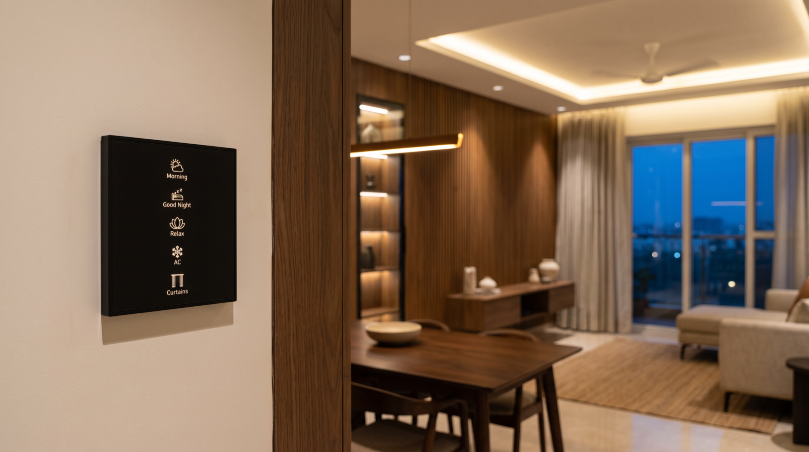
Those 36 channels are then bound to four or five engraved buttons on the wall keypads in each area — nobody operates 36 channels individually, and exposing them as 36 controls would be worse than the two switches you started with. Keypad placement and how many buttons each should carry is covered in how to plan keypads in a home.
Points to leave before plastering
Every item below is inexpensive at conduit stage and expensive or impossible afterwards. This is the list for your electrician.
- A neutral terminated at every switchboard and every keypad back-box — the single highest-value item on this list.
- An agreed channel schedule, room by room, with the fixture type, count, wattage and driver for each channel, issued as a drawing rather than described verbally on site.
- Separate circuit ways per zone with C-curve MCBs on the lighting circuits, and no single circuit carrying more than about 1,000W or thirty drivers.
- A ventilated control cabinet of at least 300 x 400mm (2BHK) or 400 x 600mm (3BHK), near the DB, reachable without a ladder, with spare DIN rail for one extra module.
- Two spare channel ways wired back to the cabinet and left capped — the cheapest future-proofing available.
- Marked driver locations above accessible false ceilings, each behind a service hatch, with run lengths inside the driver's stated limit.
- Separate conduits for low-voltage strip runs, kept away from mains runs to avoid induced noise on dimming control lines.
- A 5A point at the motor end of every curtain track at window-head height, for the motorised curtain tracks.
- Power and cabling at each planned camera and sensor position for the security hardware, decided at the same time as the lighting so the same conduit run serves both.
- An as-built drawing on handover recording every channel, its fixtures, its driver and where that driver physically sits.
Where this sits in the overall build programme is set out in when to plan home automation during construction and how to plan smart lighting for a new home.
How Pert delivers it — a designed solution, not a DIY kit
Pert is a solutions company: we design and install. For load and channel planning that means we do the arithmetic before anything is bought. We take the lighting layout and the scene list, derive the channel schedule from them, and then check every channel against its four limits — maximum derated load, minimum load, driver count and headroom — before a single module is specified. The output is a drawing your electrician can build from: the channel list room by room, the fixture and driver on each channel with its wattage, the circuit split and MCB curves, cabinet size and location, driver positions with service hatches, neutral requirements at every board, and the keypad positions with their engraving. It goes to the electrician, the false-ceiling contractor and the carpenter together, before plastering, rather than one trade at a time.
We supply the tunable and dimmable COB, strip and spot lighting, motorised curtain tracks and motors, security and sensor hardware and the wall keypads, install and commission them, and then tune the result in the finished home — setting dimming curves, minimum and maximum levels and scene ramp offsets after dark, with the real fixtures in place. That commissioning step is what removes the last of the flicker and the inrush trips, and it cannot be done from a drawing or from a box of parts. If you are comparing providers, ask each one for their channel schedule and the derating factor they apply to LED loads: the answer, or the absence of one, separates a designer from a reseller faster than any brochure. Our guide to the best home automation companies in Hyderabad covers the rest of what to check before you sign.
Building or renovating in Hyderabad? The neutral at every board, the channel schedule and the control cabinet all have to be settled before the walls are plastered — and the channel count has to come from your scenes, not from a standard switchboard drawing. Request a consultation →
Frequently asked questions
How many lights can you put on one dimmer channel?
Far fewer than the printed wattage suggests, and the limiting number is usually driver count rather than watts. A channel marked 300W is rated for a resistive filament load; LED fixtures are switched-mode electronic loads with high inrush current and imperfect power factor, so the safe working rule is to load a channel to 30 to 50 percent of its stated rating — roughly 100 to 150W of LED on a 300W trailing-edge channel. Alongside that, respect a hard limit of about 8 to 10 individual LED drivers per channel, because each driver's charging capacitor draws a very brief current spike at switch-on and ten of them firing together can weld a relay contact or nuisance-trip the MCB regardless of how small the steady-state wattage is. In practice that means about 10 to 14 recessed 7W downlights, or 6 to 8 COB spots at 12 to 15W, or roughly 10 to 15 metres of 24V strip on one channel. Then subtract for headroom: plan every channel at no more than 80 percent of the derated figure so a future fixture swap does not push it over.
Why does a single LED light flicker or glow faintly when dimmed?
Because the load is below the dimmer's minimum. Most mains dimmers need a small standing current to hold their internal electronics and switching device stable, typically declared as a minimum load of 10 to 20W. Put one 5W spot or a single 7W downlight on such a channel and the dimmer cannot sense or hold properly, which shows up as flicker at low levels, a refusal to dim smoothly through the bottom third, or a faint ghost glow when the light is supposed to be off. The fix is planning, not a gadget: never leave a channel with a single small fixture on it — group at least three or four fixtures so the channel clears its minimum comfortably, or move that fixture to a low-voltage constant-voltage channel that dims on the 24V DC side and has no minimum load problem at all. Where a single lonely fixture is unavoidable, specify a driver and dimmer pairing rated for it rather than assuming any dimmer will handle any LED.
Which lights should be grouped together on the same dimming channel?
Group by identical hardware first and by scene behaviour second. On one channel put fixtures of the same type, the same wattage, the same colour temperature and the same driver model — mixing a 24V strip with mains COB spots, or a 2700K fixture with a 4000K one, on a single channel guarantees that they dim at different rates and reach zero at different points, and the group will look broken at 20 percent even though every part is working. After that, group by what a scene needs to control separately: if you would ever want the cove on and the spots off, they must be two channels, because a scene can only address a channel, not a fixture inside it. The practical consequence in a living room is seven to nine channels rather than the two or three most drawings show — cove, general downlights, feature wall graze, artwork spots, dining pendant, dining surround, joinery and niche strips, and the switched sockets for lamps.
Do you need a neutral wire at every switchboard for smart dimming?
Yes, and it is the single most expensive thing to discover late. Older Indian wiring commonly runs only the live and the switched live to a switchboard, leaving the neutral looped at the ceiling rose. Smart dimmers and automation modules need a permanent supply to stay powered while the light is off, and without a neutral at the board they either cannot be fitted at all or have to leak a trickle of current through the load — which is precisely what causes LED ghost-glow and flicker in retrofits. Terminate a neutral at every switchboard and every keypad back-box at conduit stage, before plastering: it costs almost nothing then and means opening finished walls afterwards. While the conduits are open, also pull a spare earth to each board and leave two spare channel ways in the control cabinet, because the fixture count in a home only ever goes up.